A control system manages and regulates the behavior of a device or a system. There are many types of control systems: open-loop, closed-loop, logic, two-point, linear, proportional, and PID. This article discusses the two-point controller, also known as a Bang-Bang controller or On-off controller because once a predetermined threshold or parameter’s value is met, it turns off (or turns on). Think of your home’s HVAC and A/C units. When the home’s temperature drops below the value that you have set for it, it kicks on the heater. When it returns to that point, the heater turns off. Simple enough, right?
How Do You Operate a Two-Point Controller?
Operating a two-point temperature controller requires a data acquisition device capable of measuring temperature and one digital output bit. Digilent’s MCC DAQ line offers plenty of devices that do just that. Some devices such as the E-TC or TC-32 can run autonomously by using InstaCal. They can be configured to set the thermocouple type, temperature limits and alarms (to control the digital IO). Once powered up without the computer, these devices measure temperature and make decisions regarding the digital logic state of a particular digital bit.
These and other devices, including the USB-2408 series or USB-2416 series, can be operated by a User created program created with C++, C# or VB.NET. Additionally, higher level programs can also be used such as DASYLab or NI’s LabVIEW.
Some devices also have an option for analog output as well as digital output, and can be used for more complex control systems such as proportional and PID, but we’ll cover those at a later date.
HVAC as a Two-Point Controller
Let’s return to the aforementioned example of your home’s heating system as a two-point controller. Depending upon the age of the thermostat or HVAC controller, there may or may not be a timing element. In older homes, the thermostat is controlled by bimetal strip with a glass bulb in which there is a small amount of mercury or a small copper ball. The bimetal strip is calibrated to temperature. When the temperature goes down, the bimetal strip flexes in a direction allowing the mercury/ball to make contact with 2 electrodes, closing a circuit and turning on the boiler or furnace. Modern thermostats and HVAC controllers use “higher tech” temperature sensors such as thermistors, semiconductors, or thermocouples which are safer than mercury and easier to use in analog or digital circuitry. They also use some sort of timer or time base so as to know how often to take readings.
Home heating systems usually run on 24 VAC. This is because the control signal can be more than 10 feet from the heating system. A DC signal can show signs of attenuation when running the signal through more than 10 feet of wire. AC voltages can travel much further, but it doesn’t have to be as dangerous as using 120 or 240 VAC. 24 VAC is the standard. FYI, most doorbells run on 24 VAC. You can run the wire as far as you need, and there is no degradation to the signal.
Creating Your Own Two-Point Controller
The following application is suitable for the E-TC, TC-32 (using InstaCal). You can configure them to work autonomously by setting up temperature thresholds (alarms) for digital IO on or off, and then position them to run remotely. All you need is their respective power supplies. These device’s digital outputs operate 5V with various amperage specs.
InstaCal refers to these settings as alarms, and that is one use. Another is to use them to operate a closed loop system using any of these devices as a two point controller. As stated many HVAC systems require a 24 VAC signal to be operated. Here you see in most cases, the alarm (digital out) signal is a 5 V TTL logic signal, with low current. In all cases, none of the above can output an AC voltage. To remedy this, you can add a transistor driver and/or relay or TRIAC to control an HVAC or any other required control signal.
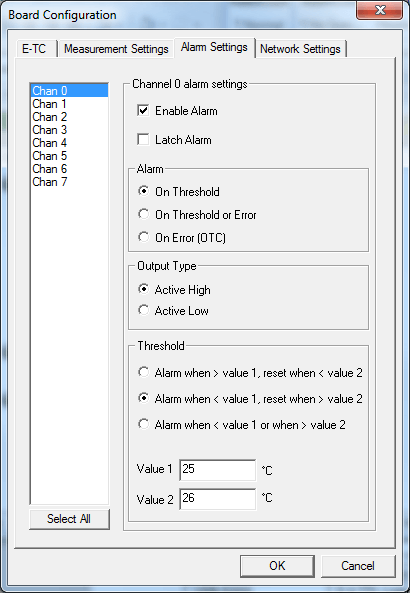
If you wanted to use channel 0 of an E-TC to monitor a room’s temperature and control a heater to keep that room at 25 °C, you can configuration the Alarm dialog box like this:
Figure 2 – InstaCal Board Settings
Here we see Channel 0’s alarm set to ‘Enabled’. It is set to turn on when a threshold is exceeded, and the output will use active high logic.
The threshold is set using the second option; to turn on the alarm when the measured temperature goes below 25 °C, and to turn off when the measured value goes above 26 °C.
Once the unit is configured, click OK, and close InstaCal.
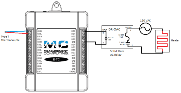
Below is a schematic for how you might wire an E-TC to a type T thermocouple, solid state relay and heater. For the purposes of discussion, let’s use a thermocouple input on an E-TC utilizing a T type thermocouple. For control we’ll use a digital output to control a fictional 120 VAC heater. The application will be created first in DASYLab, then LabVIEW, and finally in VB.NET.
The E-TC and external wiring to the heater:
Figure 3 – External Wiring to the Heater
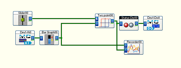
Next, the basics of implementing a two-point control in DASYLab. There are some additional settings and options used here, but let’s keep focused on the process itself.
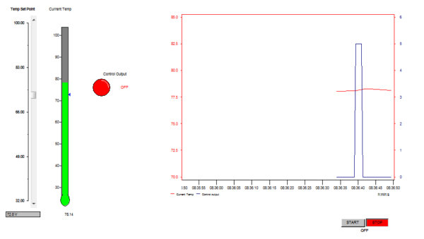
Figure 4 – DASYLab Two Point Control WorksheetFigure 5 – DASYLab Two Point Control Layout
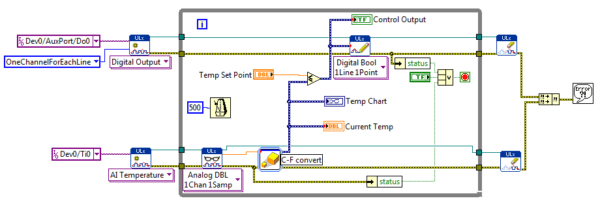
If you are using LabVIEW, that’s no problem. It doesn’t have a specific two-point controller VI, but that can easily be resolved by using a Less Than/Equal To VI as the decision maker (as seen below):
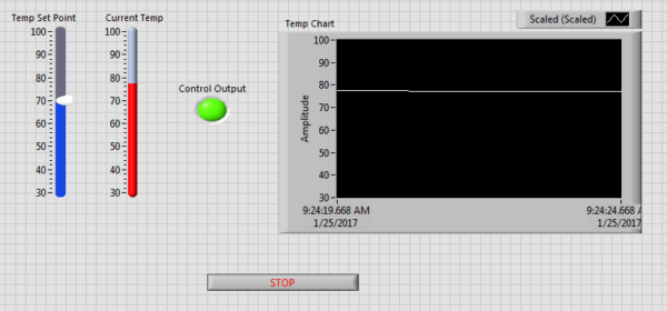
Figure 7 – And the Front Panel
Using Universal Library
Writing a program in Visual Basic .NET using the Universal Library provides greater flexibility. In DASYLab and LabVIEW, there are a few more things going on that you don’t see, like what’s being handled by the DASYLab and LabVIEW environments (finding the device, handling of errors, etc.). For device discovery, all the user needs do is pick the device from the list provided. In syntax programming for a VB app, the programmer and user can be the same person, and so the programmer/user has to generate all the code, or get it from another example app. The programmer will usually write the code segment once, and use it in as many places as possible making slight changes along the way. This is exactly what we have done below. Although the device discovery and error handling routines have been written, we’re not going to show them here, but that code can be examined and freely used HERE. Another thing not being shown is the code behind the LED, thermometer, and strip chart.
Here is the routine in the Timer_tick event used to loop through reading the thermocouple, determine if the two-point controller should be on or off, and operate the digital bit controlling the relay and heater:
If ulstat.Value <> MccDaq.ErrorInfo.ErrorCode.NoErrors Then
errhandler(ulstat)
Exit Sub
End If
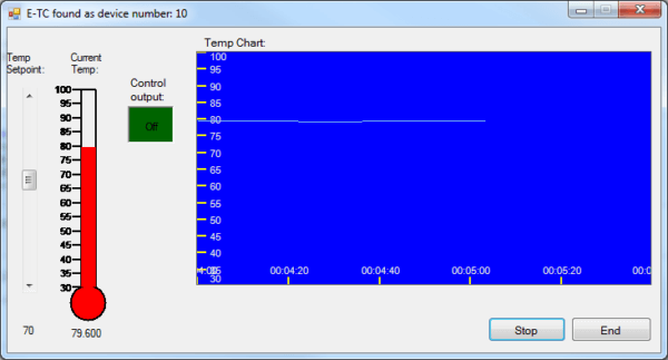
And the form view, where you can adjust the set point and monitor the performance of your system:
Figure 8 – Visual Basic .NET Form View
Conclusion
As you can see, using Digilent’s MCC temperature measurement devices and software products provide many ways to resolve the need to implement a two-point temperature controller. Pick the combination of hardware and software to meet your specific needs.
3 Comments on “Configuring A Two-Point Controller for Temperature”
Your examples seem to have neglected to provide hysteresis, which is usually essential to a 2-point controller. You either need two set points (slightly above and slightly below the desired temperature) or some timing delays to keep the output from chattering. The standard mechanical thermostats generally had about 1°–2°F of difference between the two set points (though some were adjustable). When between the set points, the current state (on or off) is maintained—when the temperature drops below the lower set point, the heater is turned on, and when the temperature rises above the upper set point the heater is turned off.
Hello. It seems that you’re an expert of this domain. Please could you help me? I have a school project which purpose is to program an FPGA that will collect the ambiant temperature and display a curve of the temperature.
please share full details with application note and budgetary prices