Getting Started with ULx for NI LabVIEW Part 1
Measurement Computing offers programming support for NI LabVIEW by way of using ULx. Included with the ULx installation is a collection of sample programs you can use and learn from to perform all manner of functions.
In general, the examples collect arrays of data but don't demonstrate the minimum effort needed to collect just a single value.
For this example, we will create a VI that can acquire one analog sample and display it on the Front Panel. I will be using a USB-1608G Series device, installed and showing up in InstaCal as board 0.
NOTE: Make sure you have closed InstaCal prior to loading NI LabVIEW!
Open NI LabVIEW and select a Blank VI. Adjust the layout of the Front Panel and Block diagram so that they are next to each other, either vertically or horizontally. This is a small project so it should all fit on your screen.
Hover your mouse over the block diagram, right click to pop up the Functions menu, select User Libraries then ULx for NI LabVIEW. Drag a Create Channel.VI onto the Block Diagram. Repeat that same process, but this time, drag a Read.VI to the Block Diagram and place to the right of the Create Channel.VI. Leave a few inches between the 2 VIs so there is room to work.
If you have not done so already, turn on the Context Sensitive Help of NI LabVIEW. To do this, click the Show Context Help (or Ctrl + H) found on the Help menu. This shows you the VI and its input/output pins.
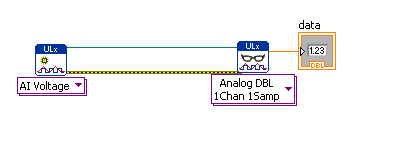
Now wire the Create Channel.VI's task out pin to the Read.VI’s task in pin, and the Create Channel.VI’s error out pin to the Read.VI’s error in pin. It should look like this:

Next, we will add a simple way to display the value read from the USB-1608G. Hover your mouse over the Read.VI, move the mouse so it is over the data pin. Use the Context Help to help you locate it if needed. When the cursor is over the data pin, it will change from an arrow to the wiring tool. When this happens, right click and select Create » Indicator. Your Block diagram will look like this:
Also notice there is a numeric display on the front panel. You’ll want to drag this a bit wider so you can see all the digits.
The next step is to tell the Create Channel.VI what physical channel of the USB-1608G to measure. Hover your mouse’s cursor over the Create Channel.VI, then move it over the Physical Channel pin, when the cursor changes to the wiring tool, right click on the pin, and select Create » Control. Your Block Diagram should look like this:

And your Front Panel will look like this:

All you need do now is click on the physical channels combo box and select Dev1/Ai0 to select channel 0 of the USB-1608G, and click on the run button to acquire a sample and display it.
If all ran correctly, your Front Panel should look something like this:

You can enhance this VI by adding error handling, a while loop, iteration timing, writing the data to file, etc. but here is where we will leave this VI, to be continued in Part 2. Save this VI to your computer as we will add to it in part 2.
This same technique can be applied to other tasks such as analog output, digital input and output, and counter input and output. You can mix and match these tasks to suit your needs. Should you need to acquire data at rates higher than software polling allows, then it is recommended you look at the other examples that are in stalled as part of ULx.
This example, written in NI LabVIEW 2009, is attached to this article.
Attachments
Getting started with simple Analog Input.llb